Friday, 24 February 2017

CNC router conversion

I recently got my hands on an automated chemical testing robot that was no longer in use. I plan on turning it into a CNC router, it will mostly be used for cutting wood and plastic but occasionally aluminium. The machine currently has adequately solid X and Y axis bearing setup however the Z axis has a basic rack and pinion design with only two rods and 4 bushings as the linear guide.


The Z axis will need to be upgraded to increase its rigidity and handle the weight of the spindle motor. As seen in the photo below the existing Z axis is mounted together with the Y axis motor inside a small, thin walled, aluminium box. The box will be scraped and all the electronics and mounting hardware will be re-used.


The left photo is looking up at the bottom of the box, the pulleys you see are the drive for the Y axis, I will be reusing these as well. The right photo shows the bearings for the Y axis and the Y axis reed switch end stops.


The bearings require a special tool (or perhaps just the right sort of pliers) which I did not have, so I came up with my own solution. It is a shaped piece of thin aluminium stock with a couple of 3mm bolts tapped into it. This allows access to the center where a bolt lays.


My tool worked great, the allen bolt is actually a cam shaft with the internal bearing riding on it and the outer ring is essentially a lock nut to keep the cam shaft in the right position. This allows you to adjust the vertical spacing between the two sets of bearings.


I was lucky enough that I had access to an old CNC gluing machine which has a small xy axis carriage. I set about to tearing it down to it's useful pieces. The photo to the right shows my spindle motor next to some of the parts from the gluing machine, I decided to use one of the gluing machines carriages to drive the z axis up and down. This meant I can reuse the belts and motor mount which saves on fabrication.


These are the linear rails and bearing blocks I got out of the gluing machine. One set of these will be used for the Z axis.


The Y axis on the chemical machine is supported by bearings both sides but only has a single side driven by a motor. That was fine when all it was doing was dropping a probe into some liquid but with a router the forces will be much higher. I will need to add a motor and belt to the non driven side.
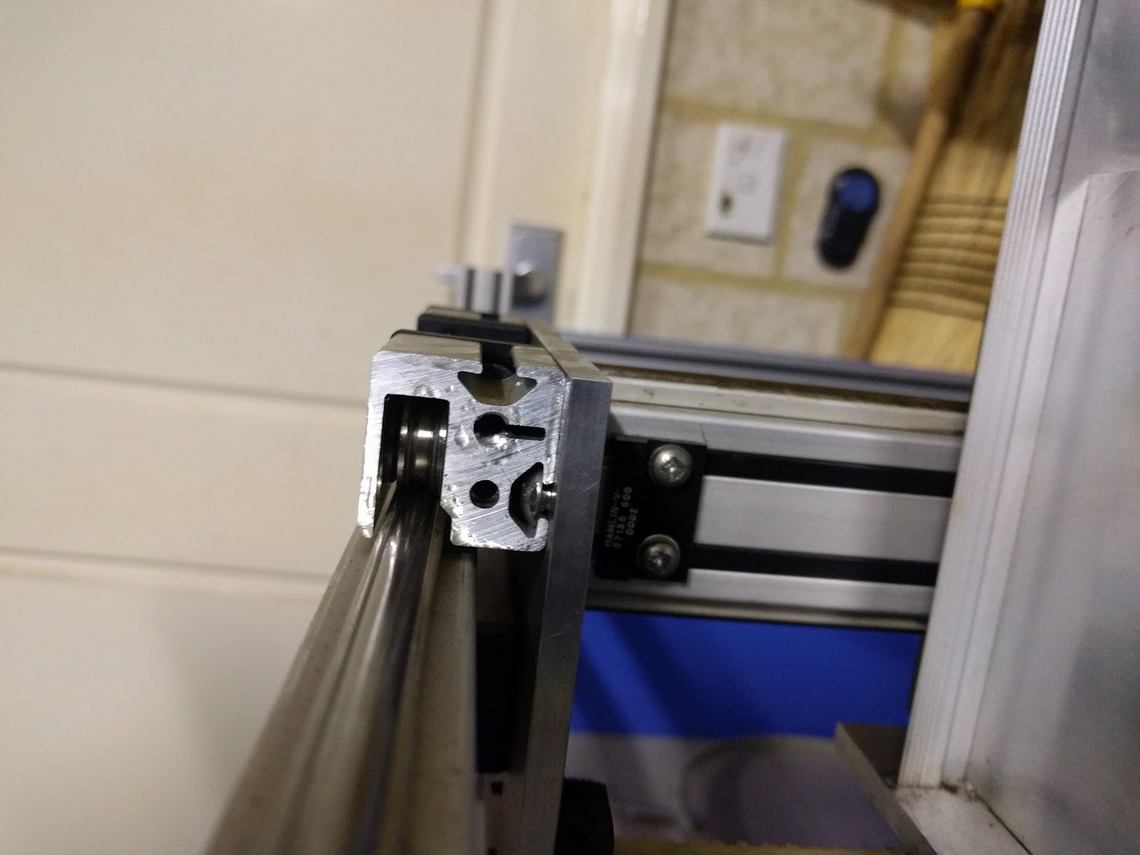

The plates that holds the Y axis rail to the X axis bearings is what the original X axis motor is mounted to so I will try and mirror this on the other side. I pulled the original non motor side plate off the machine and took all the dimensions for the bearings. I went to a shop called Di Candilo Steel City, they are a steel supplier and manufacturer so I went to their off cut section and bought a small section of aluminium plate that matched the thickness of the plate from my machine.

I had a couple of spare belts and pulleys from the same place I got the original machine from so I used these to put together the new X axis motor drive. The photo below shows the back side of this plate.


I ended up going with a Makita handheld router with 750W of power and it has a speed controller built in. This should be good enough for my purposes, I don't really have any idea how long it will last but I have found people making replacement collets for it so evidently someone has liked it enough to make aftermarket parts. The photo on the right shows a large 3D printed block to cradle the spindle motor. These mounts are very wide and are in compression so should handle the loads. The aluminium angle is from the gluing machine I pulled apart.


Constructing the Z axis was relatively simple. I used one of the glue machine axes but modified it a bit by moving the linear rail a bit and mounting the bearing block to the back of the spindle mount along with the belt latch. The motor assembly, belts and pulleys were already there so I didn't have to do any fabrication in regards to those. I tried very hard to ensure I had square holes for the Y axis bearings but my first try I was out. Luckily enough I had room to move things around and second time around it was much more true. In the photo below and left you can see the spindle motor is attached using large pipe clamps cut in half and bolted to the motor mount. The photo on the right shows the Z axis mounted to the machine without the spindle motor. For now I have the end stops attached with double sided tape, once I confirm all the motion I will drill and tap some permanent mounting holes for them.


The photo below shows the back side of the Z axis, the motor shows drives the along the Y axis using a belt and pulleys.


This photo shows most of the original control electronics pulled out of the control box. The original controller used a large industrial PLC and 3 external stepper driver boards. I have no interest in trying to re-use the PLC and from what I was told one of the stepper drivers was dead so all of that has gone to the junk pile (I'll keep the stepper drivers around for future projects). The only thing I kept from the original box is the power supply and wiring. Pictured sitting in the control box is a small Arduino based RAMPS board I was contemplating using.


For the control electronics I settled on a product called the Smoothieboard, I won't go through all the details of it here but it is a 32-bit ARM board with up to 5 stepper drivers on board, plenty of generic I/O and ethernet connectivity. I could have purchased one of these boards fully assembled online but instead I decided to build one (I actually built two at the same time for about the same cost as buying one). I used a pneumatically controlled dispenser to lay out my solder paste, hand placed all the components with tweezers then re-flowed them in a modified toaster oven. The photo below shows the Smoothieboard installed in the original control box.
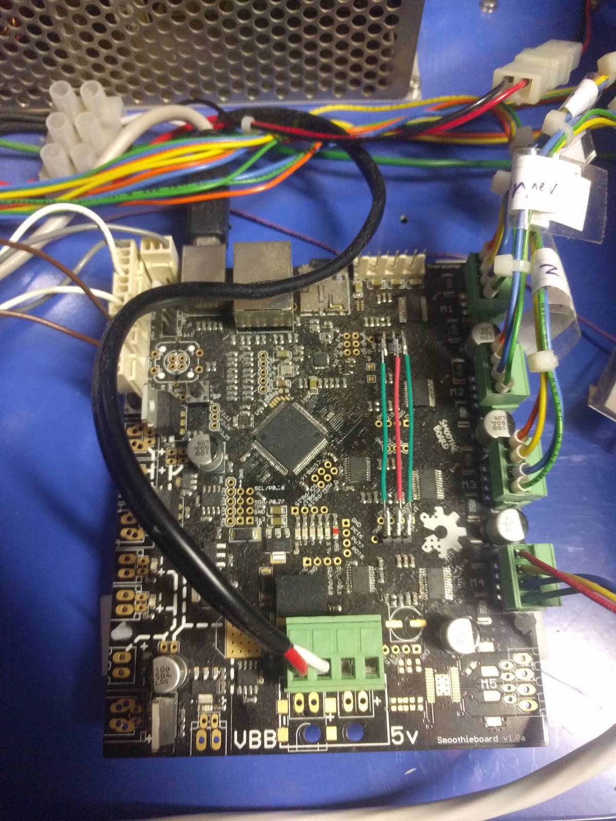

I used all of the existing wiring in the machine along with running an extra cable to drive the added X axis stepper motor. I spent a bit of time calibrating the software for the control electronics and making sure everything was reasonably square.

A post shared by @emc_technician on


I have a few things to tidy up still like rewiring the spindle motor, get speed feedback from the spindle and add a dust extraction system to keep the mess down. These are all future projects, for now I have a use for the machine which I will show in a future post. I also had the mill drill a bunch of holes in the spoilboard for mounting parts.

A post shared by @emc_technician on

Wednesday, 5 October 2016

Activate Siri with macOS Voice Commands and Automator

So a lot of us iPhone power users have gotten used to the ability to activate siri on our phones without voice commands, and now that Siri has made it on to macOS Sierra, a few of us were probably surprised to know that we couldn't activate the same feature on our much more powerful laptops with better microphones! Well there's a cool little hack that will allow you to do just that, and introduce you to a whole world of voice automation fun.

You could be laying back in your bed with your mac open on your desk, and ask it to start playing music without even having to get up, as I demonstrate in this video


I've based my instructions of this tutorial, however since my instructions use Automator instead of a keyboard shortcut, they will work on more people's setups! so go ahead and follow these instructions until instruction 10, and then instead of assigning the dictation command to a keyboard shortcut, we're going to create a workflow with Automator and run that instead.

All you need to do is open up Automator (a program that comes pre-installed with macOS that many people simply overlook) which can be found in spotlight search. Then create a new workflow


Now you simply add the action "Launch Application" which can be found by searching for it under the Utilities library, and as the Application parameter for this action we just select Siri.app


Now you save this workflow and assign the voice command to the workflow you saved. Easy!

One thing to note is that it sometimes works TOO well, in that siri will activate itself if you're listening to audio on the speakers that contains the words "hey siri"

Friday, 27 November 2015

How to set up Cloak VPN on your Asus RT or DD-WRT router using OpenVPN

Hey all!
I was quite surprised today at how little information there is out there on how to configure Cloak on non-apple devices, so I thought I'd do a little write-up to save everyone the hour or two it took me to gather all this information myself. For me, the reason I need Cloak on my router is so that I can watch American Netflix on my Chromecast (and future Apple TV hehe).

Cloak is a great VPN service that's geared towards Apple products, but its official support is limited to ONLY iOS and OSX devices, with no indication of future support of other systems (so if you want a VPN android or windows support have a look at services like ExpressVPN). on the OSX client it uses an OpenVPN profile with the following configuration (don't worry if this makes no sense):

/Applications/Cloak.app/Contents/MacOS/openvpn --client --daemon cloak --writepid /var/run/cloak-openvpn.pid --log-append /var/log/cloak.log --dev tun --lport 0 --comp-lzo --ca /.../cloakca --remote-cert-tls server --ifconfig-noexec --route-noexec --server-poll-timeout 10 --auth-user-pass --auth-nocache --auth-retry interact --management /.../cloakmgt.unix --management-client --management-query-passwords --up-delay --up-restart --plugin /Applications/Cloak.app/Contents/MacOS/cloakvpn.so --script-security 0 --verb 2 --setenv cloak_logging_uid UID --setenv cloak_plugin_server /.../cloak.pluginserver --remote ENDPOINT_1 443 tcp --remote ENDPOINT_1 443 udp --remote ENDPOINT_2 443 tcp --remote ENDPOINT_2 443 udp --remote ENDPOINT_3 443 tcp --remote ENDPOINT_3 443 udp --remote openvpn.getcloakvpn.com 443 tcp --remote openvpn.getcloakvpn.com 443 udp
And after some googling i found a gist written by davepeck (one of the guys from Cloak) that specified an OpenVPN config file for using with cloak here Awesome! But it didn't work for me :(

Nov 27 10:28:09 rc_service: waitting "start_vpnclient1" via udhcpc ...
Nov 27 10:28:10 openvpn[726]: Options error: You must define CA file (--ca) or CA path (--capath)
Nov 27 10:28:10 openvpn[726]: Use --help for more information.
So I did some playing around with the config file and eventually I got one working for me, here is where to download it  (I uncommented one line)

So here are the full instructions:

Get your router:

This is my Asus RT-AC67U. It's a fast, powerful router with a great UI (and I got it for free from work!)


Update your router firmware

Add a new VPN Client Profile
Upload the OpenVPN configuration settings provided in my gist here
Tick Import the CA file or edit the .ovpn file manually." and copy the CA from the file (including the start and finish lines) into the CA field

Click OK and Activate the VPN profile.

If everything went well, you should be exiting out of the closest exit node (in my case, Melbourne)

Now, here's where things get hacky...

Update the openVPN server in the config

If you want to exit through another country, you have to activate cloak on another device, and then resolve the domain openvpn.getcloakvpn.com to get the ip address of the exit node then replace the instances of openvpn.getcloakvpn.com with that IP. Yes, this seems like a pretty silly hack but it totally worked for me! I can't guarantee the stability of this but it's lasted me a few hours.


Now I have a portal to california, I'm free to browse the internet anonymously and American Netflix on my Chromecast!


Monday, 17 August 2015

Experimenting with soluble support materials

The main reason we wanted to have dual extrduers was to enable the printing of complex structures using a soluble support material. The materials we have been using are HIPS and ABS.  HIPS (High Impact Polystyrene) can be dissolved in Limonene, a cyclic terpene made from the leftover pulp and rind of oranges.

The first design which made use of the soluble support material was a simple gear mesh test found here on Thingiverse. The print turned out functional, but the gears had a lot of freeplay and wasn't a great example of what I believed the printer was capable of.

I wanted something challenging to print, I settled on designing a bearing, specifically a roller bearing, this suited a first design as it is relatively easy to design and print compared to a ball bearing. Using information learned from an MIT Fundamentals of Design pdf on bearings I wrote an OpenSCAD script to generate a roller bearing design given desired inner and outer diameters, you can find the script on my github.

The design went through a couple of iterations, this first version I printed had a very small gap between the inner and outer side walls, this made it very difficult to get the soluble support material out.

Below is the latest render of the bearing without the outer wall to show the internal workings, in this iteration the gap between the inner and outer sidewalls has been increased to allow more liquid flow into the internals of the bearing. The ring running through the center of the rollers is the cage, this keeps the rollers spaced correctly.

For the first print I generated more support material than needed, I rectified this and below you can see a render of the support structure less the outer wall support. One of the biggest reduction in disolving time is to adjust the slicing settings for the soluble support I used slic3r with the following settings: 
    For soluble support:
        -Extruder                       soluble material (HIPS)
        -Top solid layers                      1
        -Solid bottom layers                0
        -Perimeters                                 0
        -Solid infill threashold area   1mm^2 
    
    For bearing:
        -Extruder                                   solid material (ABS)
        -Top solid layers                     3
        -Solid bottom layers               3
        -Perimeters                               5
The removal of unnecessary support and adjustment of slicing settings keeps the amount of material to be dissolved as minimal as possible and saves on your dissolving fluid.

The final print is dissolved in limonene, it took quite some time to dissolve the support but in the end A couple of the rollers were still stuck. In the process of trying to work them loose one of the rollers snapped in half at the cage so I will be reprinting again. It can handle a filament spool but I don't think it would survive at anything but slow speeds.

See here for the design on thingiverse or on my github.

I might try redesigning the cage in the future, in replace of the single cage there would be a cage either end of the rollers. This would make the support material between the roller and cage easier to dissolve. However it has a couple of downsides, it will mean more support material to support a second cage and restrict the side openings.

Matt

Monday, 10 August 2015

The Hydra: a Dual Head i3-Based 3D Printer

Laserphile's most extensive project so far has to be our 3D printer, dubbed The Hydra. The Hydra evolved naturally from it's ancestor, the Prusa i3 which we have modified and tinkered with for 2 years to get to where we are now. Although still under development it's a fast, thermally efficient, dual head printer with a custom, laser-cut acrylic case and uses the Bowden mechanism for extrusion. Here's a run down of the process we went through to get to where we are now.

Evolution

Genesis

Using the designs of the Prusa i3, created by Josef Prusa we had the aluminium frame cut using an industrial water jet cutter and sourced as much of the electronics and hardware from local stores. Altronics had all the cabling, the arduino micro, various electronics and a small selection of nuts and bolts. The smooth and threaded rods came from various local hardware stores.

Once we had gathered all the pieces together, the printer came together really quickly. Within a few hours we had assembled most of the printer, and we had an awesome 3-axis robot that moved around with serial commands within a few days.

Warping

After finishing construction we had some issues relating to the reliability of prints, namely getting prints to stick to the heated bed. We mitigated this by increasing the temperature of the heat bed, this was helped by insulating the underside of the bed with styrofoam wrapped in Aluminium foil to decrease thermal losses and adding a layer of Kapton tape to the print surface to increase the print adhesion. This worked great but after some months of use we found the heated bed (which is essentially just a fibreglass circuit board) had started to warp, so we decided to splash out and get a piece of glass cut (actually only cost $5 from a local glass cutter). Having the glass made a world of difference, it made levelling the print bed much easier and the build surface was now perfectly flat. No more would prints fail to stick!

Software

Our printer management software of choice has been Octoprint which runs on our Raspberry Pi and provides an excellent graphical interface to the Arduino micro controller using a web server. You can upload your gCode files to it and initiate prints along with the ability to manually control temperatures and movement, very useful for calibration. In the photo below you can see the raspberryPi mounted on the right hand side of the frame.

Bowden Extruder

Now that we had unlocked the "relatively stable print quality" achievement with our mostly vanilla i3, we really started to tinker with things. The fist major deviation from the i3 blueprint came with our implementation of a bowden extruder, it was a huge upgrade to our heavy, direct drive extruder that was causing a lot of backlash on the X axis. The first extruder we used was a slightly modified QU-BD MBE V9 direct drive extruder which we turned into a bowden setup with a few custom parts, later on we switched to E3D V6 hotends and re-designed our own bowden motor mount. The different designs for the motor mount can be found in this repository.
QU-BD direct drive extruder
QU-BD bowden extruder
E3d V6 hot end

Two heads are better than one

By far the biggest upgrade we have done to the printer is add a second extruder to it. This allows it to do a few extra things that are just impossible with a single extruder, first it can do two colours (see below) and it can do different plastic types. The main reason for the upgrade is so it can print with a soluble support plastic along with the normal plastic, this opens up a realm of possibilities.


Laserphile Hydra dual head extruder systemLaserphile Hydra 3D printed dice with multiple materials

Acrylic Case

Our most recent mod is probably our most unique. Although our cider box thermal solution was actually pretty effective, to further combat the issues we had with warping we designed an acrylic case to try and retain some of the heat from the heated bed and block any draughts. Although it took a while to refine the design using Open SCAD, it was really surprising how easily this case came together after we got the pieces laser cut. You can find the design files here.

Laserphile Hydra 3D printer with cardboard case
Before
Laserphile Hydra with custom acrylic case
After

The Future

Our plan is to continue to work on improving the print reliability, and increasing the z axis print height. This will require modifications to the heat bed mount and hot end mounts as these are the parts most vulnerable to vibrations and effect the print height.
Laserphile Hydra 3D printer on desk
Printer desk

I recently designed and printed a roller bearing to be printed in one piece and then the support material holding the rollers in place can be dissolved away to create a working bearing. I'll discuss this in a future post.

Matt

Saturday, 11 April 2015

Bluetooth DMX controller update

After a couple of queries from people interested in this project i have decided to post an update to what we have been working on. We have produced a production prototype of the Bluetooth DMX controller to bring it a step closer to being ready for a small run production sample. I also threw together a very basic Android application using MITs application inventor, this let us test the first prototype as well as show off the proof of concept to friends.


The hardware

There were a couple of design iterations building up to the construction of the first production prototype. The production prototype boards are based around an Arduino mini controller and a Roving Networks RN-42 SMD bluetooth module.

The component list in full:
  • Arduino mini
  • RN-42 SMD bluetooth module
  • MAX485 RS-485 serial interface
  • 5V TO-220 regulator
  • 3.3V TO-220 regulator
  • 3 * 10µF electrolytic capacitors
  • 2.5mm barrel jack power connector

You can see the component layout in this early design revision. from the right most side we have the XLR connector, the 8 pin MAX485 IC, the 5v regulator with capacitor above, socket layout for the arduino mini, surface mount pad layout for the RN-42 bluetooth module, 3.3v regulator, two capacitors and the 2.5mm barrel jack power connector. Note that all the thru-hole components are on the non copper side and the bluetooth SMD module is soldered straight onto the copper side of the printed circuit board.


The following is the layout of the first unit built, it has the power components all to the right hand side of the board to simplify the track layout, and have both power and DMX connectors coming out the one end.


For production the design is transferred to a Kinsten positive photo resist board by covering the bare circuit board with the printed design (printed on transparency paper) and exposing it to UV light, in our case using a specially designed UV flruo lightbox. After exposure the baord is still sensitive to light so it must be quickly developed in the Kinsten developer solution. Finally it is ready to etch, I did this using Ferric chloride and an old electric stove in an open area (the fumes can be quite noxious). Last two steps are to give the etched board a coat of circuit board lacquer to prevent the copper oxidising in the air and drilling out the holes for components.

You can just see 4 identical circuits laid out on the large circuit board on the table.


The first constructed prototype.


The current hardware plan is to make a small production run of units with 3d printed cases. We will give these units out to friends so we can get some feedback on what could be changed.

The Android software

The Android software is currently very basic, being able to only address 5 DMX channels via sliders on the touch screen. I built this quickly using the MIT app inventor, a very useful tool for quickly and easily making android applications.
I set up the first 2 channels to be able to strobe between 0 and the selected value on the slider (maximum 255).


I plan on re-writing the application from scratch and will be working to add the ability to assign a group of DMX channels to individual devices (like multi colour LED lights or moving heads). This will allow for a simple and intuitive interface for any screen size.
Following that I will work on enabling the ability to pre-set scenes and animations to be enabled on cue or run on a pre-set timeline.This will bring the functionality of the control software to be on par or better than low end dedicated DMX lighting desks.


Stay tuned.
Matt

Saturday, 1 June 2013

Bluetooth DMX512 controller

DMX512 (Digital MultipleX) is a standard for digital communication networks that are commonly used to control stage lighting and effects. It was originally intended as a standardized method for controlling light dimmers, which, prior to DMX512, had employed various incompatible proprietary protocols. It soon became the primary method for linking controllers to dimmers and special effects devices such as fog machines and intelligent lights. DMX has also expanded to uses in non-theatrical interior and architectural lighting, at scales ranging from strings of Christmas lights to electronic billboards.


The need for a DMX lighting controller came about after I bought my first piece of lighting equipment, a DUNE 3 colour laser projector. This unit has automatic show functions and a sound reactive function, but it isn't enough, I wanted to be able to control the functions of my laser. 
After doing a bit of research into current products available on the market, I found they were either based on a physical lighting desk (expensive hardware), or propriety software systems based on a computer communicating with a usb DMX controller (expensive software/hardware).  In my research I also came across an Arduino software library capable of driving DMX signals, the hardware side of things is very simple, it is based around an RS485 serial communication IC with some supporting circuitry. 

The use of an Arduino microcontroller means that any manner of control could be used, anything from push buttons, to variable resistors, to accelerometer or the idea I had, which was to connect via Bluetooth to my phone. Okay, so it isn't a particularly new idea, but so far I cannot find anyone who has tried doing this open source. I want to be able to drop all of my gear down at an event, plug the power in, and immediately be able to control everything via a wireless connection from my phone. DMX512 supports daisy chaining devices along the same DMX bus, this removes the hassle of wiring back to central location, this plus wireless control should mean a very quick and pain free set up.


This is at the breadboard stage, I have a power supply in the background there supplying 3.3v to the Arduino and Bluetooth module.


I was testing out the functionality with my RGB LED strobe.


 I have changed to a different Arduino module here. The prototype board seen holds the two voltage regulators, a MAX485 chip and all the wiring to go between the Bluetooth and Arduino.


This is how the first prototype looks. My next two steps with the hardware is to design a custom PCB and a 3D printed case to hold everything together a bit more securely.
Looking at the software side of things and it is non existent, the phone and Arduino are currently just communicating via a Bluetooth serial terminal, the DMX library on the Arduino interprets commands and applies them to the DMX bus. The mobile device software side will be something relatively simple and allow for basic control of the DMX channels with possibly some programmable functions.


Just to share, this is my road case of stage equipment, it includes an RGB LED strobe, Dune red, green and cyan laser projector, and a Dune 400 smoke machine.