Friday 29 December 2017

Camera based spherical touch surface for an interactive light show


For several years I have been fascinated with geodesic domes and LED lighting. To bring together these two passions of mine I, along with a few friends, plan to fit 5725 LEDs inside of a 6 meter diameter geodesic dome. To make it interactive there will be a touch based controller in the middle of the 6 meter dome to allow people interact in real time with the lights around them.


The display will be made up of 20 triangles with around 300 LEDs in each, this makes it necessary for quite an interesting layout and control scheme which is what we have spent the last few months working out. This project will be split up into a few different posts. We will start with the touch input device and related software. Next I will discuss the software and hardware for controlling the LED array. Later comes the labor intensive tasks of building the steel dome, assembling the LED panels and all the wiring to go between everything.

A spherical touch input device is not a novel idea and has been implemented many times before. I found inspiration in a Microsoft research paper found here (pdf), I decided to try a similar approach using cheap commercially available hardware and open source software. I commissioned a local plastics forming company to make a ~500mm diameter dome from translucent polycarbonate plastic using a pressure forming tool. This was chosen because it was the cheapest option available, this has a downside in that the opacity is not consistent. At the peak of the dome the plastic has been stretched the most is significantly thinner than around the lower edges. I was able to work around this in software which I will explain later.


A wide angle monochrome USB camera from ebay is used for sensing, I specifically asked the vendor to supply the camera without an infra red cut filter. In front of the camera is an infra red longpass filter to get rid of all the visible light coming into the camera. Inside the lower edge of the dome I placed infra red LED strips (made by de-soldering a white LED strip and adding my own digi-key bought IR LEDs), these flood the inside of the dome with infra red light. When a finger comes into contact with the outside of the dome it reflects the infra red light, this is picked up by the camera. I used this method because there will be a lot of coloured lights around and want to give my camera the best chance of picking up touches. The image below is what the camera sees.


The software for the touch input uses openCV and python to manipulate and extract information captured by the camera. The image processing involves the following process:
  1. A calibration image is taken with no finger touches and is stored. This gives us our baseline to compare against. 
  2. Subsequent images taken by the camera have the calibration image subtracted from them. This results in only the bright reflections caused by finger touches to show up. 
  3. A blob detection function in openCV is used to find the coordinates of the bright spots. This gives us our touch coordinates which can be used for anything. 
The video below shows the dome working as a mouse input for my computer. At this point I had not switched over to using IR LEDs and was relying on visible light.


Next post I will talk about the software and hardware required for driving the 5725 LEDs. If you are interested in the software all our source files are available on github here.

Monday 16 October 2017

1953 Austin truck repairs

My father bought this 1953 Austin K9 truck from the local shire in 1992, the shire had used it as a fire truck so it has a big (rusty) water tank on the back. It has sat in his shed since then, it was used occasionally for watering plants around his property until the water tank in it rusted out. We still bring it out every now and then to enjoy just driving it to the beach or through the bush as it is quite a unique experience. 

 
Due to the age of the truck there are a few problems we need to fix before we drive it again, the first of these we fixed was the fuel pump. The original fuel pump was mechanical and used a flexible diaphragm and a one way valve to pump the fuel, unfortunately the diaphragm started to disintegrate so as a temporary fix we had a gravity fed fuel tank. This wasn't great as we couldn't go very far and you had to climb up to fill it with fuel.The fuel pump issue was easily fixed with a new 12v electric pump and some tubing, we also added in a new fuel filter just in case.

The next major issue is the water pump, the bearings were so sloppy the shaft was visibly sagging and there was a significant leak of coolant out the front. This photo shows the front of the engine with the water pump already removed. It isn't much fun working on this thing as all of the nuts and bolts are very odd sizes. We were switching back and forth between various imperial and metric sizes all day.


Below you can see the front section of the water pump which houses the bearings and the water seal butts up against it. The impeller is in the middle and the shaft on the right. The plan is to replace the bearings. which involved taking them to a bearings supplier and getting direct replacements. Replacing the water seal however was not so easy as it was already hacked together and had no life left in it. We could not find a direct replacement and so purchased a modern seal and decided to modify the pump to suit. For this I will be using my newly modified CNC router.


I bolted the pump housing down with some 8mm rod I added some thread to as I didn't have any bolts long enough, these went through diagonal mounting holes of the housing, this let me have some control on how flat the whole thing was. The impeller was much easier to secure down.


The following video shows the milling operation cutting into the cast housing. The plan is to glue in a lapped stainless steel washer to be a nice surface for the modern pump seal to seat against. 


The next step was bringing the outer diameter of the impeller down to suit the modern water seal. I needed to find the center as a reference to my CAD so I used my multi-meter to do a continuity test between the router and the part. By jogging the machine very slowly I would hit the edge of the circle and my multi-meter would buzz, I took note of those co-ordinates and tested 2 other points, this let me calculate the center.


Video of the operation, all my path files were generated using Fusion 360.


End result is good as we wanted it the same diameter as the shaft.


Here it is after fixing the fuel pump and water pump. I want to do some more restoration or at least a few things to stop it deteriorating any further. Some day I would love to take it on the Variety Bash  which is a charity event where old vehicles are driven through Western Australia to raise money for disadvantaged children, but that is well in the future.


Wednesday 11 October 2017

Platypus Hardware Hacking 101: Finding UART and Getting Root

Intro

Last night I gave a talk and helped run a workshop at Platypus Facts and Hacks Melbourne. In the workshop we identified UART on a router using a USB to UART adapter to talk to the device, and managed to pop a shell or two. These techniques could be used to exploit nearly any kind of Internet of Shit device, since a staggering proportion of these devices have UART shells as a way to test the device.

FTDI basics

FTDI Breakout
FTDI is the name of a company that makes chips which have USB on one side and UART / RS232 / TTL / Serial. Since there is more than one manufacturer or USB to UART adapters, FTDI is just synonymous with a USB to UART adapter from any manufacturer since it's less syllables (e.g. Biro == pen).

You can pick up one of these adapters for about $5 on ebay. Just make sure your device has good drivers, and if you like to be versatile, get a chip that can do 3.3V and 5V.

Once you grab your FTDI chip and install the drivers, the device will show up as a COM port on a Windows computer or a "file" in /dev/ on unix like /dev/tty.usbserial
If you're on unix, a good way to figure out exactly which file is the FTDI chip, is to ls /dev/ with the device not plugged in, then plug it in, wait a second and ls /dev/ again. Any new devices that show up must be the FTDI chip!

Now you'll need to use a serial monitor to send and recieve serial. On Windows, you can use Putty to interface with the TTL, and unix, you can just use the screen or picocom command.
To talk to a TTY device, you have to specify the baud rate, which is the number of bits per second that the device talks at. If you set the wrong baud rate, your terminal will end up printing out garbage or nothing at all, but it means you're connected to something.

Typically a FTDI cable has 4 to 6 pins:
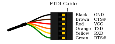
FTDI Pinout
  • Ground
  • Clear to Send
  • +5v
  • Transmit Asynchronous Data output.
  • Receive Asynchronous Data input.
  • Request to send
Some of these pins are vestigial leftovers from a time where computers were not fast enough to send and receive data all at once, but we don't need to use these pins for our purposes.

Identifying UART

Typically we would let the device power itself normally, and then only connect the GND, TX and RX pins (not VCC!) to the uart test pads. Finding them can be quite difficult, but the best method is to look up the router on OpenWRT, and they will usually have pretty good documentation on where the pins are.
UART Pins
If someone else hasn't written up your board, but you can see a collection of test pads, you can identify which test pads correspond to which uart pins with a little bit of heuristics. The more advanced way would be to look for a group of 3 or more test pads, and trace them back to the nearest chip, then look up what each of the pins on that chip do. You could also purchase an expensive logic analyser to do the work for you, but by far the cheapest way involves only a multimeter. We know that at a minimum, the UART header will have GND, TX, RX (and usually VCC) so we can use the multimeter to try and identify these pins.

Don't forget to write up the information you find on somewhere like OpenWRT or your own blog if you can't find the research elsewhere. It will save someone else having to go through the same process as you, and you will get mad internet points.

Identify Ground.

Electronic engineers love ground, so are going to be many points on your board that are connected to ground. Every ground pin is connected to one another, and usually the shielding on different ports on the PCB is also connected to ground. So with the router disconnected from power, have a look for either a group of circular test pads, a row of through holes or a row of male 0.1" headers and begin probing.

You can test continuity to ground for each of your test pads to determine which of them are ground. Sometimes the PCB silkscreen will help you out by labelling ground for you

Identifying VCC

VCC is the name given to the positive voltage rail. Sometimes a complex circuit board can have multiple positive rails at different voltages, but a router will usually run on a mobile system-on-chip that runs on 3.3V. With the device powered on, you can test the voltage difference between ground and each pin. Just be careful not to directly bridge ground and VCC since it could fry your power supply. To do this, set your multimeter to measure in the range of 2 to 5 Volts DC (not AC).

Depending on the circuitry behind the UART, the VCC will usually stay at a stable voltage of exactly 3.3 or 5 Volts, but the TX and RX pins might have a less stable, lower voltage, particularly during boot when data is being sent over serial.

You may also notice that VCC will have a thicker trace going to the pin compared to TX and RX on some PCBs, and VCC can be labelled on the PCB as Vcc, Vbb, V+, Vee, Vdd or Vss. Just remember that the power supplied to the router by the wall (usually a 12V barrel jack or a 5V USB) will most likely be stepped down to a different voltage on the board.

Another hot tip: to be sure that a pin is VCC, try to identify multiple points that are at VCC relative to ground at different points on the board. Typically you might measure a strong continuity between these pins, even when the board is off, but you might only measure a "blip" of continuity between VCC and TX / RX.

Identifying TX and Baud rate

Now that we've identified which pins are VCC and GND, we can hook GND of the FTDI up to GND of the router, and probe different pads to try and find a pin that's transmitting serial. Simply connect the RX pin of your UART to different points on the board, selecting common baud rates like 115200 and 9600, rebooting the router each time. If you get garbage on your serial monitor, that means your pin is sending some kind of signal, which means you should simply try a different baud rate. This can be a tedius but rewarding process. Be careful not to plug any of the pins you identified as VCC on the board in to your FTDI's RX or you could break stuff. This script may be of use as well! https://github.com/devttys0/baudrate/blob/master/baudrate.py

Identifying RX

Now that you've got your TX and know what baud rate to listen to, you can start trying to find the RX pin on your board. RX is usually right next to TX but just be careful again not to plug VCC in to the TX on your FTDI. You just connect the TX pin of your FTDI to each potential RX pad on the board, typing stuff in to your serial monitor each time and if your serial monitor starts behaving like a TTY then boom! You've got UART baby. Depending on what serial port you end up on, you could be listening to the debug logs of a subprocessor on the board, so you may have to keep hunting until you get a serial port connected to the main SoC that resembles a linux TTY with stuff like kernel messages and diagnostics.

No UART? No Problem.

If you weren't able to identify the UART, you can still have some fun with JTAG, but that requires special hardware like a Bus Pirate, and who even has $25?

Getting Shell

Now that you've got UART, depending on your choice of router you may need to do some trickery to get a shell. Carefully read the output of the router when it boots, and look for stuff like "press return now for console". Other kinds of routers require you to type something like "system console" or "shell" to get a shell, but you may need to type "help" to figure out the exact syntax it requires. If you have no luck figuring out how to get shell, some google dorking will be helpful here. Look for research or manufacturer documentation on your router or a similar router from the same manufacturer. Consider the fact that cheaper routers from obscure manufacurers like the ones you find on Alibaba will often be rebrands of other manufacturers. Otherwise, fuzzing techniques may be required here.

Rooting

If you've got a shell, and you're really lucky, sometimes it will drop you straight in to root, otherwise it will ask you for a login / password, This is where you can try to guess the manufacturer's root password, which will typically be hardcoded in the device firmware and selected from a handful of root passwords that a given manufacturer uses. Again, you'll need to do some dorking to get some research or docco that mentions this root password. If your dorking is unsuccessful you may have to brute force it, which is much easier to do on unix. This would typically involve piping a password cracking utility like Hydra to the UART and listening to the response, but you will probably need to write some kind of Python script to set up and manage your pipes.

Post-coital Router Shenanigans

Now that you've rooted your router, the sky is the limit. If the router has enough memory you can install all kinds of fun things on it. Often smaller routers will have extremely limited storage, so you may need to commandeer one of the USB ports on the router to store install extra packages on a hidden USB drive.

If you want to easily install linux packages and don't mind being easily detected, you can reflash the firmware to something like OpenWRT or TomatoRT which comes with the opkg package maanger.

Some ideas:

  • Persist on a target network
  • Sniff traffic to discover services on the network
  • Mess with the network's routing table and DNS to re-direct traffic to a box you control
  • Bitcoin mining?
  • ????
  • Profit

Wednesday 29 March 2017

Making signs for Blazing Swan

Over the past couple of months myself and a couple of friends have been making signs for our theme camp, Moon Base, for Blazing Swan 2017. The main signage will be going on our entrance way (pictured below).

Making the sign body and wiring up the electronics took the vast amount of time in this project. There was several hours of milling to make the various parts of the sign. The lettering inlays are made of lightly spray painted poly-carbonate sheets I cut out in my mill.
The sign below is for our (water) bar.  All of the signs were cut on my CNC mill and are made of veneered plywood marketed as Formply. I used this after trying MDF and the Formply cuts much cleaner as it chips a lot more than the MDF which turns into more dust sized particles.


The signs will be mounted above our entrance way to our camp on a sheet of plywood so I have epoxied some nuts on the inside of the signs so I can bolt them onto the entrance without any visible fasteners.
 

The signage will be out in the elements for several days so I built the electronics into a sealed ABS box. All the connectors are reasonably waterproof, if the weather gets ridiculously wet I can easily detach the box and bring it under cover. We are using a Teensy 3.2 micro controller to drive the main logo and MOON BASE signs and an Arduino Pro Mini micro controller driving another smaller sign.

I attached all of the LEDs to the milled out pieces of plywood and painted all the necessary areas white to reflect the light as much as possible. The logo has 5 individual strip driven through an Ethernet cable with a two core power cable. The MOON BASE signs use microphone cable and connectors which are cheap and readily available.


I used silicone to attach the poly-carbonate lettering to the main body of the signs. Double sided tape and short wood screws hold the backing onto the main body. After assembling I then went and painted a couple of layer around the edges and sealed the gap between the backing and main body. This should all ensure the signs are weatherproof.

My friend Jon wrote the Arduino sketch to run the signage so all points for the animations go to him. The source code can be found at github.com/vanbujm/Moonbase. We used the FastLED library to drive the LEDs at the low level.

Friday 24 February 2017

CNC router conversion

I recently got my hands on an automated chemical testing robot that was no longer in use. I plan on turning it into a CNC router, it will mostly be used for cutting wood and plastic but occasionally aluminium. The machine currently has adequately solid X and Y axis bearing setup however the Z axis has a basic rack and pinion design with only two rods and 4 bushings as the linear guide.


The Z axis will need to be upgraded to increase its rigidity and handle the weight of the spindle motor. As seen in the photo below the existing Z axis is mounted together with the Y axis motor inside a small, thin walled, aluminium box. The box will be scraped and all the electronics and mounting hardware will be re-used.


The left photo is looking up at the bottom of the box, the pulleys you see are the drive for the Y axis, I will be reusing these as well. The right photo shows the bearings for the Y axis and the Y axis reed switch end stops.


The bearings require a special tool (or perhaps just the right sort of pliers) which I did not have, so I came up with my own solution. It is a shaped piece of thin aluminium stock with a couple of 3mm bolts tapped into it. This allows access to the center where a bolt lays.


My tool worked great, the allen bolt is actually a cam shaft with the internal bearing riding on it and the outer ring is essentially a lock nut to keep the cam shaft in the right position. This allows you to adjust the vertical spacing between the two sets of bearings.


I was lucky enough that I had access to an old CNC gluing machine which has a small xy axis carriage. I set about to tearing it down to it's useful pieces. The photo to the right shows my spindle motor next to some of the parts from the gluing machine, I decided to use one of the gluing machines carriages to drive the z axis up and down. This meant I can reuse the belts and motor mount which saves on fabrication.


These are the linear rails and bearing blocks I got out of the gluing machine. One set of these will be used for the Z axis.


The Y axis on the chemical machine is supported by bearings both sides but only has a single side driven by a motor. That was fine when all it was doing was dropping a probe into some liquid but with a router the forces will be much higher. I will need to add a motor and belt to the non driven side.


The plates that holds the Y axis rail to the X axis bearings is what the original X axis motor is mounted to so I will try and mirror this on the other side. I pulled the original non motor side plate off the machine and took all the dimensions for the bearings. I went to a shop called Di Candilo Steel City, they are a steel supplier and manufacturer so I went to their off cut section and bought a small section of aluminium plate that matched the thickness of the plate from my machine.

I had a couple of spare belts and pulleys from the same place I got the original machine from so I used these to put together the new X axis motor drive. The photo below shows the back side of this plate.


I ended up going with a Makita handheld router with 750W of power and it has a speed controller built in. This should be good enough for my purposes, I don't really have any idea how long it will last but I have found people making replacement collets for it so evidently someone has liked it enough to make aftermarket parts. The photo on the right shows a large 3D printed block to cradle the spindle motor. These mounts are very wide and are in compression so should handle the loads. The aluminium angle is from the gluing machine I pulled apart.


Constructing the Z axis was relatively simple. I used one of the glue machine axes but modified it a bit by moving the linear rail a bit and mounting the bearing block to the back of the spindle mount along with the belt latch. The motor assembly, belts and pulleys were already there so I didn't have to do any fabrication in regards to those. I tried very hard to ensure I had square holes for the Y axis bearings but my first try I was out. Luckily enough I had room to move things around and second time around it was much more true. In the photo below and left you can see the spindle motor is attached using large pipe clamps cut in half and bolted to the motor mount. The photo on the right shows the Z axis mounted to the machine without the spindle motor. For now I have the end stops attached with double sided tape, once I confirm all the motion I will drill and tap some permanent mounting holes for them.


The photo below shows the back side of the Z axis, the motor shows drives the along the Y axis using a belt and pulleys.


This photo shows most of the original control electronics pulled out of the control box. The original controller used a large industrial PLC and 3 external stepper driver boards. I have no interest in trying to re-use the PLC and from what I was told one of the stepper drivers was dead so all of that has gone to the junk pile (I'll keep the stepper drivers around for future projects). The only thing I kept from the original box is the power supply and wiring. Pictured sitting in the control box is a small Arduino based RAMPS board I was contemplating using.


For the control electronics I settled on a product called the Smoothieboard, I won't go through all the details of it here but it is a 32-bit ARM board with up to 5 stepper drivers on board, plenty of generic I/O and ethernet connectivity. I could have purchased one of these boards fully assembled online but instead I decided to build one (I actually built two at the same time for about the same cost as buying one). I used a pneumatically controlled dispenser to lay out my solder paste, hand placed all the components with tweezers then re-flowed them in a modified toaster oven. The photo below shows the Smoothieboard installed in the original control box.


I used all of the existing wiring in the machine along with running an extra cable to drive the added X axis stepper motor. I spent a bit of time calibrating the software for the control electronics and making sure everything was reasonably square.

A post shared by @emc_technician on


I have a few things to tidy up still like rewiring the spindle motor, get speed feedback from the spindle and add a dust extraction system to keep the mess down. These are all future projects, for now I have a use for the machine which I will show in a future post. I also had the mill drill a bunch of holes in the spoilboard for mounting parts.

A post shared by @emc_technician on